Answer
The database design process can be divided into six steps. The E-R model is most relevant to the first three steps.
- Requirements Analysis: The very first step in designing a database application is to understand what data is to be stored in the database, what applications must be built on top of it and what operations are most frequent and subject to performance requirements. In other words, we must find out what the users want from the database.
- Conceptual Database Design: The information gathered in the requirements analysis step is used to develop a high-level description of the data to be stored in the database, along with the constraints that are known to hold over this data. This step is often carried out using the E-R model or a similar high-level data model.
- Logical Database Design: We must choose a DBMS to implement our database design and convert the conceptual database design into a database schema in the data model of the chosen DBMS. Task here is to convert E-R schema into relational database schema.
- Schema Refinement: The fourth step in database design is to analyze the collection of relations in our relational database schema to identify potential problems and to refine it.
- Physical Database Design: In this step we must consider typical expected workloads that our database must support and further refine the database design to ensure that it meets desired performance criteria. This step may simply involve building indexes on some tables and clustering some tables, or it may involve a substantial redesign of parts of the database schema obtained from the earlier design steps.
- Security Design: In this step, we identify different user groups and different roles played by various users (e.g., the development team for a product, the customer support representatives, and the product manager). For each role and user group, we must identify the parts of the database that they must be able to access and the parts of the database that they should not be allowed to access and take steps to ensure that they can access only the necessary parts.
Logical Database Design
During logical design we transform the E-R diagrams that were developed during conceptual design into relational database schemas.
Transforming E-R diagrams to relations is a relatively straightforward process with a well- defined set of rules. In fact, many CASE tools can automatically perform many of the conversion steps. However, it is important that we understand the steps in this process for three reasons:
- CASE tools often cannot model more complex data relationships such as ternary relationships and supertype/subtype relationships. For these situations we may have to perform the steps manually.
- There are sometimes legitimate alternatives where we will need to choose a particular solution.
- We must be prepared to perform a quality check on the results obtained with a CASE tool.
The ER model is convenient for representing an initial, high-level database design. Given an ER diagram describing a database, there is a standard approach to generating a relational database schema that closely approximates the ER design. We now describe how to translate an ER diagram into a collection of tables with associated constraints, i.e., a relational database schema.
Entity Sets to Tables
An entity set is mapped to a relation in a straightforward way: Each attribute of the entity set becomes an attribute of the table.
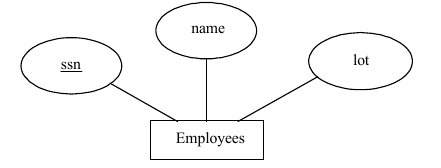
Consider the Employees entity set with attributes ssn, name, and lot shown in Figure 1.
A possible instance of the Employees entity set, containing three Employees entities, is shown in Figure 2 in tabular format.
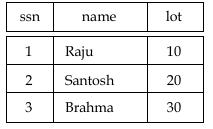
The following SQL statement captures the preceding information, including the domain constraints and key information:
CREATE TABLE Employees (ssn CHAR (11),
name CHAR (30),
lot INTEGER,
PRIMARY KEY (ssn) )
Relationship Sets (without Constraints) to Tables: A relationship set, like an entity set, is mapped to a relation in the relation model. To represent a relationship, we must be able to identify each participating entity and give values to the descriptive attributes of the relationship. Thus, the attributes of the relation include:
- The primary key attributes of each participating entity set, as foreign key fields.
- The descriptive attributes of the relationship set.
The set of non-descriptive attributes is a superkey for the relation. If there are no key constraints, this set of attributes is a candidate key.
Consider the Works_In2 relationship set shown in Figure 3. Each department has offices in several locations and we want to record the locations at which each employee works.
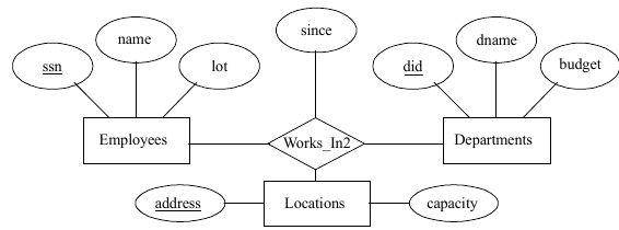
All the available information about the Works_In2 table is captured by the following SQL definition:
CREATE TABLE Works_In2 (ssn CHAR(11),
did INTEGER,
address CHAR(20),
since DATE,
PRIMARY KEY(ssn, did, address),
FOREIGN KEY(ssn) REFERENCES employees,
FOREIGN KEY(address)REFERENCESLocations,
FOREIGN KEY(did) REFERENCES Departments)
The address, did, and ssn fields cannot take on null values. Because these fields are part of the primary key for Works_In2, a NOT NULL constraint is implicit for each of these fields. These constraint ensures that these fields uniquely identify a department, an employee, and a location in each tuple of Works_In.
Translating Relationship Sets with Key Constrains: If a relationship set involves n entity sets and some m of them are linked via arrows in the ER diagram, the key for any one of these m entity sets constitutes a key for the relation to which the relationship set is mapped. Thus we have m candidate keys, and one of these should be designated as the primary key.
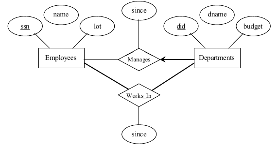
Consider the relationship set Manages shown in Figure 4. The table corresponding to Manages has the attributes ssn, did, since. However, because each department has at most one manager, no two tuples can have the same did value but differ on the ssn value. A consequence of this observation is that did is itself a key for Manages; indeed, the set did, ssn is not a key (because it is not minimal). The Manages relation can be defined using the following SQL statement:
All the available information about the Works_In2 table is captured by the following SQL definition:
CREATE TABLE Works_In2 (ssn CHAR(11),
did INTEGER,
address CHAR(20), since DATE,
PRIMARY KEY(ssn, did, address),
FOREIGN KEY(ssn) REFERENCES employees, FOREIGN KEY(address)REFERENCESLocations, FOREIGN KEY(did) REFERENCES Departments)
The address, did, and ssn fields cannot take on null values. Because these fields are part of the primary key for Works_In2, a NOT NULL constraint is implicit for each of these fields. These constraint ensures that these fields uniquely identify a department, an employee, and a location in each tuple of Works_In.
Translating Relationship Sets with Key Constrains: If a relationship set involves n entity sets and some m of them are linked via arrows in the ER diagram, the key for any one of these m entity sets constitutes a key for the relation to which the relationship set is mapped. Thus we have m candidate keys, and one of these should be designated as the primary key.
Consider the relationship set Manages shown in Figure 7.4. The table corresponding to Manages has the attributes ssn, did, since. However, because each department has at most one manager, no two tuples can have the same did value but differ on the ssn value. A consequence of this observation is that did is itself a key for Manages; indeed, the set did, ssn is not a key (because it is not minimal). The Manages relation can be defined using the following SQL statement:

CREATE TABLE Manages (ssn CHAR(11),
Did INTEGER,
since DATE,
PRIMARY KEY(did),
FOREIGN KEY(ssn) REFERENCES Employees,
FOREIGN KEY(did) REFERENCES Departments )
A second approach to translating a relationship set with key constraints is often superior because it avoids creating a distinct table for the relationship set.
This approach eliminates the need for a separate Manages relation, and queries asking for a department’s manager can be answered without combining information from two relations. The only drawback to this approach is that space could be wasted if several departments have no managers. In this case the added fields would have to be filled with null values. The first translation (using a separate table for Manages) avoids this inefficiency, but some important queries require us to combine information from two relations, which can be a slow operation.
The following SQL statement, defining a Dept. Mgr relation that captures the information in both Departments and Manages, illustrates the second approach to translating relationship sets with key constraints:
CREATE TABLE Dept_Mgr (did INTEGER
dname CHAR(20),
budget REAL,
ssn CHAR(11),
since DATE,
PRIMARY KEY(did),
FOREIGN KEY(ssn)REFERENCES Employees)
Translating Relationship Sets with Participation Constraints: Consider the ER diagram in Figure 7.5, which shows two relationship sets, Manages and Works. In Every department is required to have a manager, due to the participation constraint, and at most one manager, due to the key constraint.
CREATE TABLE Dept_Mgr( did INTEGER
dname CHAR(20),
budget REAL,
ssn CHAR(11) NOT NULL,
since DATE, PRIMARY KEY(did),
FOREIGN KEY (ssn)REFERENCESEmployees,
ON DELETE NO ACTION )
Table constraints and assertions can be specified using the null power of the SQL query language and are very expressive, but also very expensive to check and enforce.
Example: We cannot enforce the participation constraints on the Works_In relation without using these general constraint.
To ensure total participation of Departments in Works_In, we have to guarantee that every did value in Departments appears in a tuple of Works_In.
Translating Weak Entity Sets: A weak entity set always participates in a one-to-many binary relationship and has a key constraint and total participation. The weak entity has only a partial key. Also, when an owner entity is deleted, we want all owned weak entities to be deleted.
Consider the Dependents weak entity set shown in Figure 6, with partial key pname. A Dependents entity can be identified uniquely only if we take the key of the owning Employees entity and the pname of the Dependents entity and the Dependents entity must be deleted if the owning Employees entity is deleted.
We can capture the desired semantics with the following definition of the Dep-Policy relation: CREATE TABLE Dep_Policy (pname CHAR(20),
age INTEGER,
cost REAL,
ssn CHAR(11),
PRIMARY KEY(pname, ssn),
FOREIGN KEY (ssn) REFERENCES Employees,
ONDELETECASCADE )

The primary key is pname, ssn, since Dependent is a weak entity.
Translating Class Hierarchies: We present the two basic approaches to handling ISA hierarchies by applying them to the ER diagram.
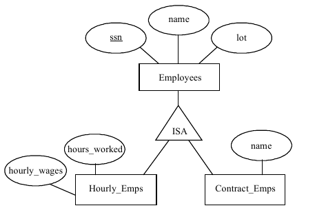
- We can map each of the entity sets Employees, Hourly_Emps, and Contract_Emps to a distinct relation. The relation for Hourly_Emps includes the hourly_wages and hours_worked attributes of Hourly_Emps. It also contains the key attributes of the superclass, which serve as the primary key for Hourly_Emps, as well as a foreign key referencing the superclass (Employees). For each Hourly_Emps entity, the value of the name and lot attributes are stored in the corresponding row of the superclass (Employees).
- We can create just two relations, corresponding to Hourly_Emps and Contract_Emps. The relation for Hourly_Emps includes all the attributes of Hourly_Emps as well as all the attributes of Employees (i.e., ssn, name, lot, hourly_wages, hours_worked).
The first approach is general and is always applicable. Queries in which we want to examine all employees and do not care about the attributes specific to the subclasses are handled easily using the Employees relation.
The second approach is not applicable if we have employees who are neither hourly employees nor contract employees, since there is no ways to store such employees. Also, if an employee is both an Hourly_Emps and a Contract_Emps entity, then the name and lot values are stored twice. This duplication can lead to some of the anomalies.
Translating ER Diagrams with Aggregation: Translating aggregation into the relational model is easy because there is not real distinction between entities and relationships in the relational model.
Consider the ER diagram shown in Figure 8. The Employees, Project, and Departments entity sets and the Sponsors relationship set are mapped as described in previous sections. For the Monitors relationship set, we create a relation with the following attributes: the key attributes of Employees (ssn), the key attributes of Sponsors (did, pid), and the descriptive attributes of Monitors (until).
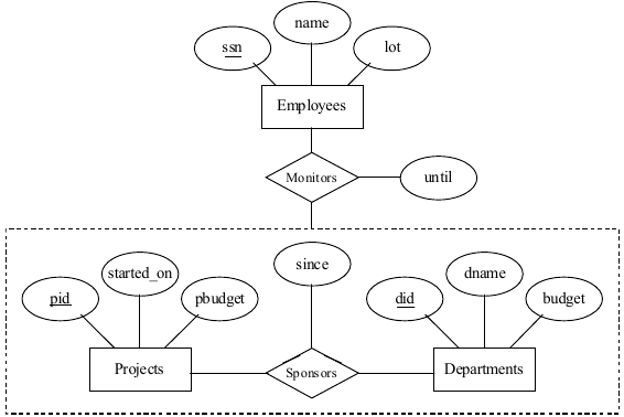
Consider the Sponsors relation. It has attributes pid, did, and since, and in general we need it (in addition to Monitors) for two reasons:
- We have to record the descriptive attributes (in our example, since) of the Sponsors relationship.
- Not every sponsorship has a monitor, and thus some pid, did pairs in the Sponsors relation may not appear in the Monitors relation.
However, if Sponsors has no descriptive attributes and has total participation in Monitors, every possible instance of the Sponsors relation can be obtained by looking at the pid, didcolumns of the Monitors relation. Thus, we need not store the Sponsors relation in this case.
Total Views: 49
