Answer:
Process layout is also known as functional layout. Similar machines or similar operations are located at one place as per the functions. For example, as will be apparent from Figure 1, all milling operations are carried out at one place while all lathes are kept at a separate location. Grinding, milling or finishing operations are carried out in separate locations. This functional grouping of facilities is useful for job production and non-repetitive manufacturing environment.

1. Process Layout and Material Handling Costs
In process layouts, one of the principles of paramount importance is that centers between which frequent trips or interactions are required should be placed close to one another.
This has implications in all manner of organizations; in a manufacturing plant, it minimizes materials handling costs; in a warehouse, stock picking costs can be reduced by storing items typically needed for the same order next one another; in a retail store, minimizing customer search and travel time improves customer convenience; in an office where people or departments must interact frequently are located near one another – both communication and cooperation often improve and coordination between departments can be less challenging.
There are both quantitative and semi-quantitative methods available for process layouts. Load- Distance Model is a simple mathematical model that captures costs to identify a location that minimizes the total weighted loads moving into and out of the facility. Another popular technique similar to the Load Distance Model for plant layout is the Travel Chart Technique. In this, we start from an initial layout, which may be the existing layout. The designer concentrates only on the critical points of the layout. Critical points are generally the areas, which have high volume- distance movement of materials. The designer attempts to modify the layout so that there is maximum improvement in the critical points.
Spiral Analysis
In certain types of layout problems, numerical flow of items between departments is either impractical to obtain or does not reveal the qualitative factors that may be crucial to the placement decision. In these situations, a semi quantitative technique like the Spiral Analysis can be used.
Spiral Analysis involves:
- Developing a relationship chart showing the degree of importance of having each department located adjacent to every other department.
- From this chart, an activity relationship diagram, similar to the flow graph is obtained, and is used for illustrating material handling between departments.
The objective of the spiral analysis is to arrange the departments in such a manner that the transportation costs of material handling are minimized. The analysis tries to find an option that provides the most direct flow of material between different departments.
Anand Parvat Industries plans to redesign the layout of its factory. The factory produces five major products. The initial layout plan is shown in Figure 1. In addition to incoming and outgoing stores, the factory has 6 departments. This data with the flow paths and volume for the different products is captured in Table 1.

In the table, the first column represents a product or a group of products. The second column represents the volume the product or the product group constitutes of the total flow in the layout. The third column shows the sequence of departments through which the product passes. For example, Product ‘I’ will go to the lathe department, from there it will go to shaping, then drilling, milling, grinding and finally to the Inspection Department before the product is stocked (refer Figure 2). The second column represents the percentage volume of the product group.
The total percentage volume of all the product groups will always be less than or equal to 100 per cent. In the example, it is less than 100 per cent. In order to simplify the problem, similar to ABC analysis of inventory systems, products that do not have significant effect on the total production pattern, have not been shown in Table 1. However, care must be taken to ensure all significant products and product groups are included.

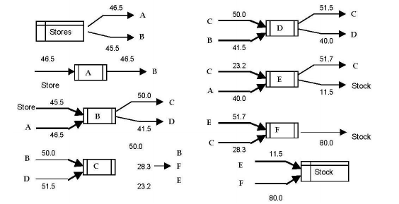
The input-output information on all the departments is computed and reflected in a schematic diagram. This is called the Material Flow Diagram. The schematic material flow diagram for our example is shown as Figure 3. The steps involved in creating the material flow diagram in the Spiral Method are:
- Draw a circle to represent each department or activity area.
- On the left side of the circle draw a line to represent incoming material from each activity, which immediately precedes the activity of interest for any product group.
- On each line to the circle indicate the quantity or per cent of total activity between the two sequence steps.
- At the right of the circle draw a connecting line that denotes where the material has to go when the operation has been completed.
- These lines tell us the quantity or percentage of total activity represented by the completed material.
These five steps give schematic representation of various departments and their material inflow and outflow. Remember, totals have to tally. For example, take the store figures. The total that leaves the store has to equal 91.5, the figure given in Table 1. Similarly, the total reaching ‘stock’ will also be 91.5. You also have to ensure that inputs and outs are balanced for each activity or department.
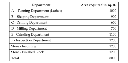
Space requirements also need to be computed. Based on the size and number of machines to be installed and the space available for the layout, the minimum space required is worked out. The requirement of space for each department, for Anand Parvat Industries, is shown in Table 2.

The spiral method works under following assumptions:
- The department shape is a combination of square and rectangles.
- The area of a department varies only slightly with peripheral changes in its shape.
The solution is arrived at by trial and error. The following steps are taken:
- The activity area is located. Each activity is located in such a manner that the serviced area and servicing areas are located with a common periphery.
- Around each of the service activity areas arrange their subsequent servicing or serviced areas, again maintaining necessary areas assignment for each.
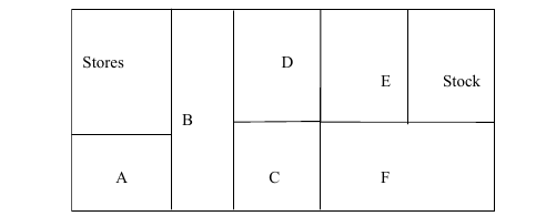
This process is continued until all departments have been located. Using this schematic, the departments should be so arranged that a department has at least some common boundary with each of the departments from which it receives material or to which it delivers material. This will ensure that material from a department is moved to another department with minimum cost. This is a trial and error procedure. It does not guarantee that an optimal solution will be obtained. Also, the solution may not be unique. One of the possible arrangements by this method for our example is shown in Figure 3.

Computerized Relative Allocation of Facilities Technique (CRAFT)
A number of computerized layout programs have been developed since the 1970s to help devise good process layouts. One such program that is widely applied is the Computerized Relative Allocation of Facilities Technique (CRAFT). The CRAFT method also follows the same basic idea as the ‘Travel Chart Technique’, but with some operational differences. It requires a load matrix and a distance matrix as initial inputs, but in addition, it also requires a cost to be computed per unit distance traveled, say, 1.50 per meter moved.
With these inputs and an initial layout in the program, CRAFT tries to improve the relative placement of the departments as measured by total material handling cost for the layout. The relationship that it uses is similar to the Load Distance Model:
Material handling cost between departments = Number of loads × Rectilinear distance between department centroids × Cost per unit distance.
The program simulates different arrangements of layout and then makes improvements by exchanging pairs of departments iteratively until no further cost reductions are possible.
2. Advantages and Disadvantages of Process Layout
Process Layout is best suited for non-standardized products; where there is a low volume, high variety manufacturing environment; where the market requires frequent change in product design; in job-shop manufacturing; and for setups where very expensive or specialized machines like CNC milling, coordinate measuring machine etc., are required to be used. Its advantages are:
- Initial investment in process layout is low.
- Varied degree of machine utilization may be achieved in process layout, as machines are not dedicated to any single product.
- There is greater flexibility and scope of expansion.
- High product variety can be easily handled, therefore different product designs and varying production volumes can be easily adopted.
- The overhead cost is low.
- Breakdown of one machine does not result in total stoppage of production. Maintenance of machines is relatively easy as it can be scheduled without greatly impacting production.
- Easy, effective and specialized supervision of each function area is easy to achieve. With different departments for different processes, better teamwork can be achieved.
- There is low setup and maintenance cost compared to other layouts.
Though the advantages outweigh the disadvantages in job shops and batch production, there are some disadvantages of Process Layout:
- There is high degree of material handling. Parts may have to backtrack in the same department.
- Large work in process inventory is common. This may lead to more storage area.
- Workers are more skilled. This is because of variety in products and difference in design, therefore, labour cost is higher.
- Total cycle time is high. This is due to waiting in different departments and longer material flow.
- Inspection is more frequent which result in higher supervision cost.
- It is difficult to fix responsibility for a defect or quality problem. The work moves in different departments in which the machine preference is not fixed. Therefore, which machine or which operator was faulty during a quality lapse may be difficult to trace in some cases.
- The production planning and control is relatively difficult.
With the changing perceptions of consumers, many feel that process layout is best limited to cases where the volumes are so low and the differences between products are so great that line flow processes, batching, and cellular manufacturing are not feasible.
Total Views: 22
